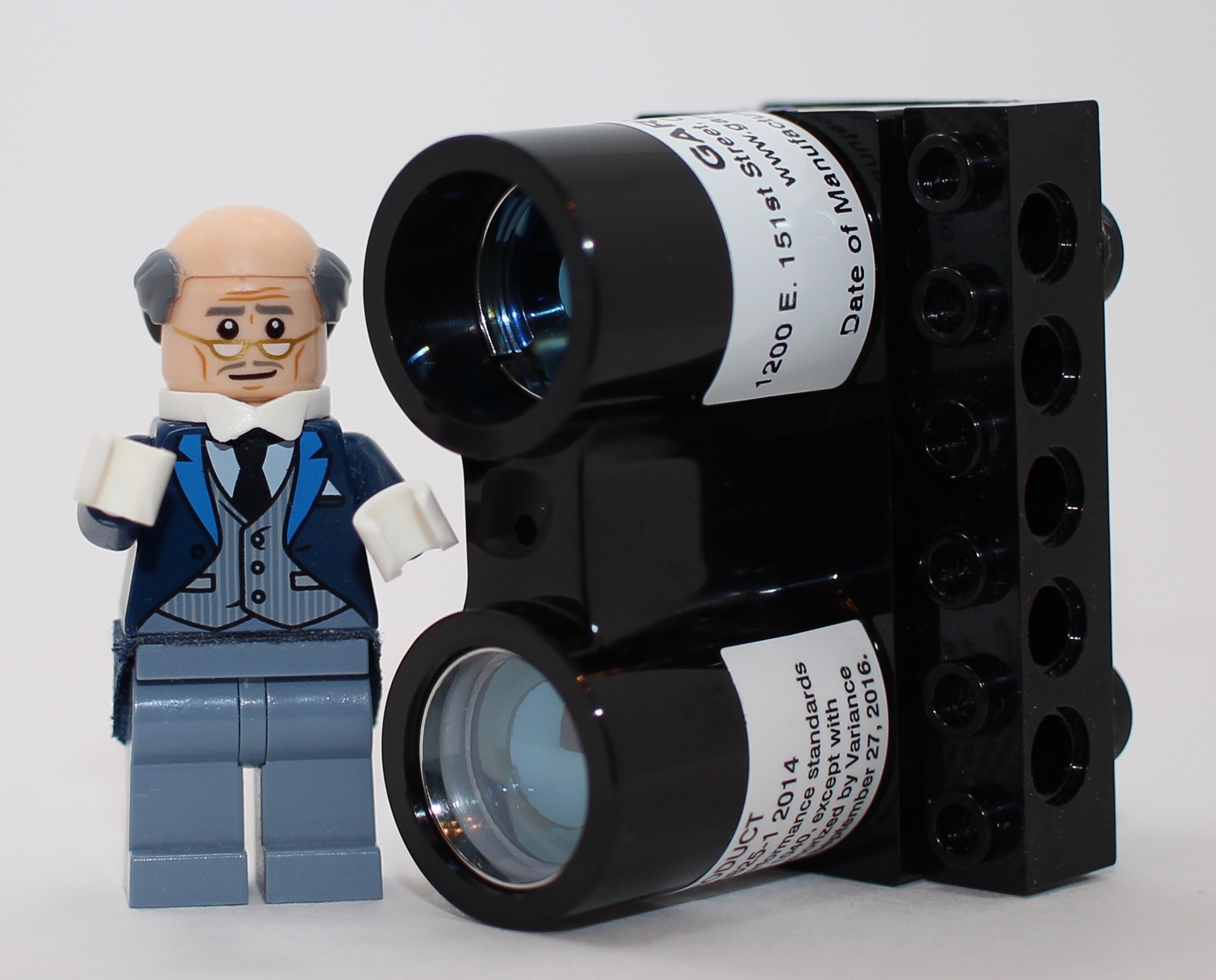
LEGO Lidar

Lidar is a fascinating technology—I’ve made a career out of it. So I’ve been looking for a way to build a LEGO-based lidar. Until recently, small lidar sensors have been either too expensive, too short a range capability to be interesting, or too complex in host computer interface. Not any more! There’s a new lidar sensor by Garmin called LIDAR-Lite 3 with a range capability of 40-meters at a cost of $150. It’s available at either of my favorite electronics distributors of RobotShop (robotshop.com) or SparkFun (sparkfun.com). The sensor is pictured above with a minor modification of glueing on a Technic brick so that the sensor can be connected to LEGO.
To get data from the lidar, there are two interface options. There’s an I2C interface and a pulsewidth modulation (PWM) output. I’m still struggling to figure out I2C protocol, and will get there one day. But when I saw the PWM, I went that direction for the LIDAR-Lite. I followed the documentation from Garmin of explaining how to make the PWM connection. In a nutshell, there’s a wire connection to drive logic low to start the flow of data from LIDAR-Lite. A PWM signal then continuously flows from another wire. A look at the PWM signal is shown in the oscilloscope screen shot below. The pulse width gives a length of 10-microseconds for every 10-centimeters of measured range. So in the example in the screenshot a target 2.2-meters away gives a pulse width of 2.2-milliseconds.

I used a Raspberry Pi to communicate with the LIDAR-Lite. A GPIO pin on the Raspberry Pi provides the logic transition to start data flow and another pin takes input from the PWM signal. To measure pulse width, I used a Python program to wait for a leading edge to occur, then set a counter incrementing until the falling edge occurs. In other words:
count = 0
GPIO.wait_for_edge(monitor_pin.GPIO.RISING)
while GPIO.input(monitor_pin):
count = count + 1
time.sleep(0.00001)
This count level is calibrated (one calibration is sufficient) by using either the oscilloscope view or by measuring the distance to target with a tape measure. Using the Raspberry Pi also allows a convenient interface to Mindstorms via the BrickPi3 by Dexter Industries (dexterindustries.com). So I used an EV3 Large Motor to scan the lidar view in azimuth angle. The setup is shown in the video below. Measurement data is displayed on a Grove display, also hosted on the BrickPi3 (see my blog post "I2C on BrickPi3").
There are many interesting things to do with the lidar—the subject of upcoming blog posts.
